The Heart Tattoo Circuit Board
Jeremy Elson, August 2017
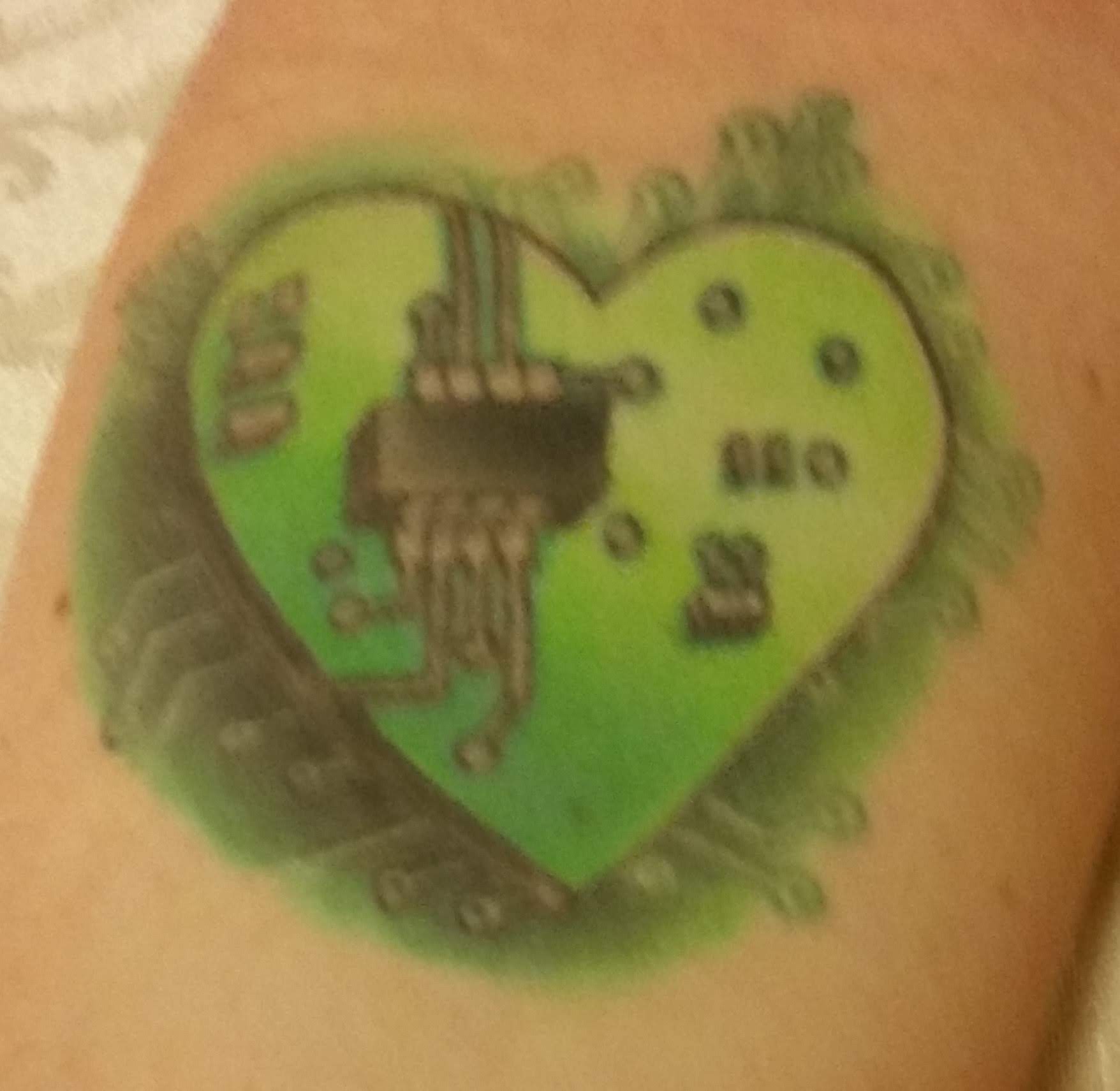
This story starts with my friend Missa’s arm.
She has a tattoo of a circuit board in the shape of a heart on her arm. One evening I had an idea: I should design a real circuit board that looks just like her tattoo, but that actually works! Her birthday was a couple months off and I thought it might make a unique gift.
The design was a fun challenge. Normally you’d start with what a circuit needs to accomplish, and work forward to figure out what it should look like. In this case I was going the other way: starting with what the circuit should look like and working backwards to figure out what it should do.
A complication was that the art seemed to be drawn by someone who wasn’t an electrical engineer. There are parts depicted as non-functional, such as traces that go all the way to the edge of the board and don’t connect to anything. Many of the rectangular components are “surface mount,” meaning they’d need traces running to them to be electrically connected, but had no traces visible.
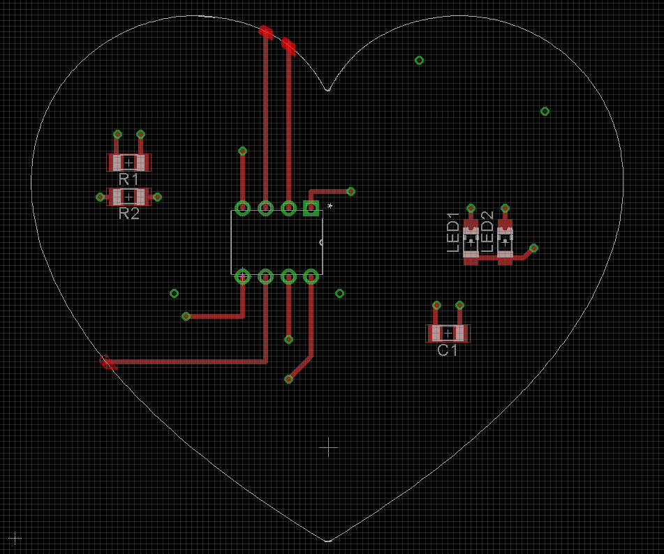
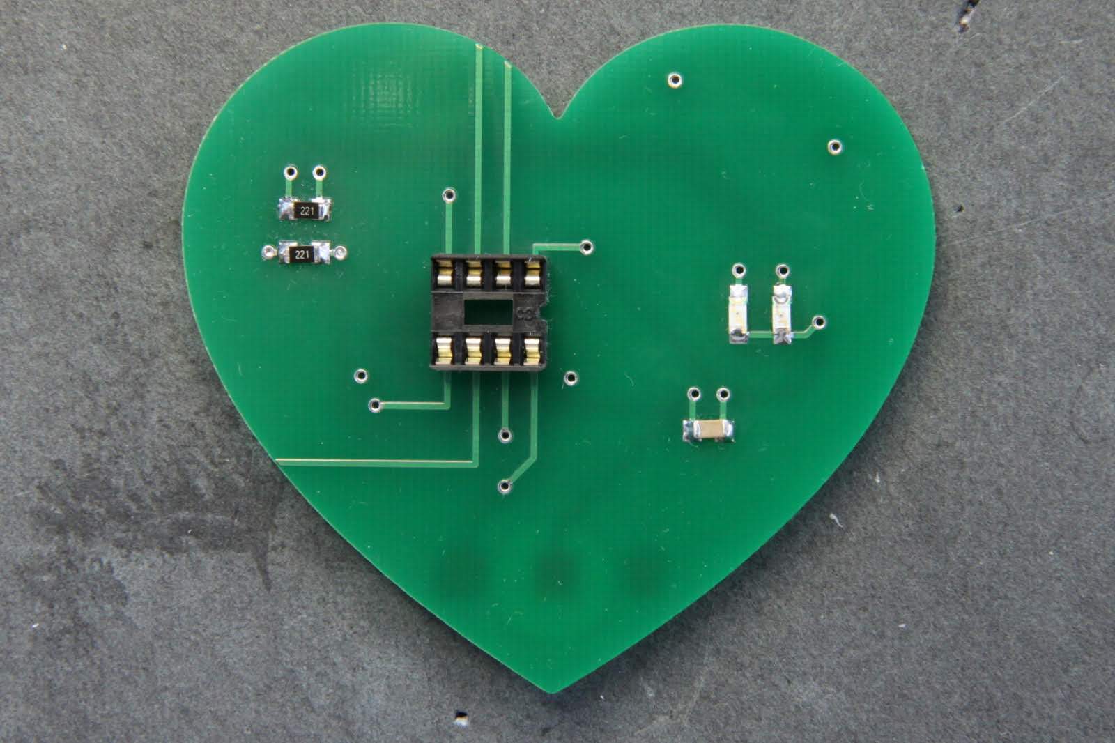
On the right is the board layout I came up with after a few hours of thought and tinkering. I tried to match every component depicted on the tattoo one-for-one with components on the final board. The tattoo shows an 8-pin chip, so I used an 8-pin Atmel microcontroller, the attiny85. I decided to make the rectangles on the right little LEDs (one red, one green), the lower-right rectangle a capacitor, and the rectangles on the left the current-clamping resistors for the LEDs.
The art showed 3 of the chip’s 8 pins being routed uselessly into oblivion, off the edge of the board. This left me with 5 pins to work with. Luckily, there was a chip orientation such that the 5 pins with useful traces depicted matched the 5 real chip pins I needed: power, ground, reset, and two I/O pins to control the two LEDs.
I added some useless vias that don’t go anywhere (the green circles) to match the art, even though they don’t do anything.
The artist took artistic license creating the tattoo, so I took “engineering license” and added a couple of functioning vias and short traces, the minimum needed to make the board work while keeping it visually as close as possible to the tattoo.
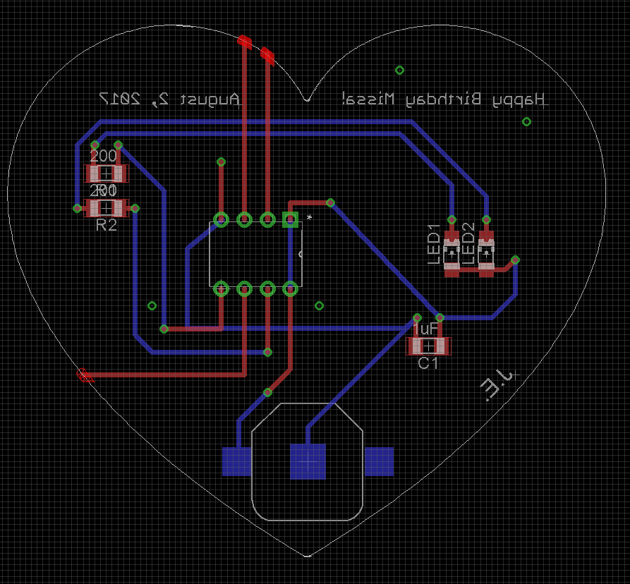
Here’s an “x-ray vision” view of the front (red) and back (blue) of the board. The red traces are designed to look just like the tattoo; the blue are what I used to connect the reds as needed so the board would operate. The big rectangular-ish thing at the bottom is a battery holder for a 12mm lithium coin cell. I wanted a battery that was small enough to fit at the bottom of the heart, but with enough current capacity to drive LEDs, and common enough that Missa would be able to find replacement batteries easily. Wikipedia’s summary of coin cells was invaluable, along with Amazon product searches to see which batteries were widely available. I ended up picking a CR1225, a good tradeoff between size and a relatively high (5mA) pulse discharge rate, enough to run a couple of 2mA LEDs.
I also wrote “Happy Birthday Missa!” and her birthday’s date. The text is on the back, which is why it appears reversed in this x-ray vision view. I didn’t dare put it on the front because that had to match the tattoo exactly!
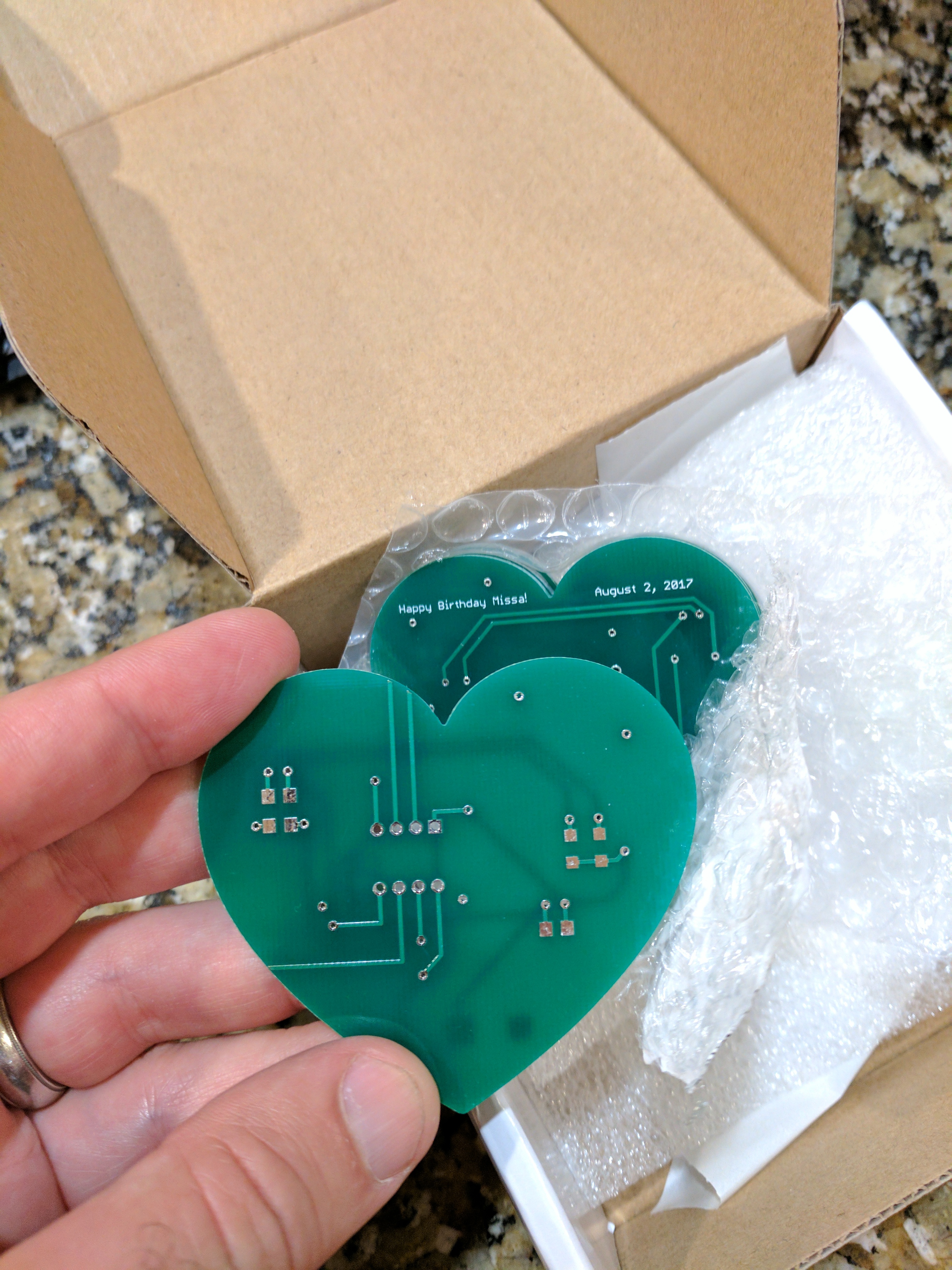
I sent the board design off to my favorite fab house—PCBWay, in China—and, boom! A week later, 5 copies arrived. It still amazes me that it’s so easy to go from a drawing on my computer to a physical object.
This was my first time designing a non-rectangular board, so it was a learning experience for me. The heart shape is from clip art I found on the web; I looked at a few pages of hearts until I found one that looked similar to Missa’s. I imported it into Adobe Illustrator and adjusted the shape to make the heart match the tattoo a little better. Then I exported the heart shape as a DXF file and imported it into the Board Outline layer of my PCB design software, Eagle, using this excellent tutorial.
I hadn’t done much surface-mount soldering at the time, so this was another learning experience! I usually use through-hole parts, but the tattoo depicted surface-mount parts, so…
After soldering the small components on with tweezers, the board was gunked up with flux and didn’t look very pretty. I took my friend David’s excellent suggestion: washing it down with 99.9% isopropyl alcohol. The board came beautifully clean with it.
On the right is the board in operation! I wrote software so that the green LED blinks “Happy Birthday Missa” in Morse code and the red blinks out all the prime numbers from 2 to 23. The code is available on GitHub. I wrote it using RULOS, the tiny microcontroller “operating system” (I use that term loosely) my friend Jon and I originally wrote for the Rocket Ship Treehouse starting in 2009. I factored the Morse-code generator into its own library.
I ended up writing a little simulator so I could develop the software on my desktop computer and see the output on the screen; it’s much easier to debug problems and get everything working when you can print useful messages like “keying dot” rather than debugging using only two LEDs as output.
Once I got the software working in the simulator, I compiled it for the microcontroller, popped the chip into the board, and it worked on the first try!
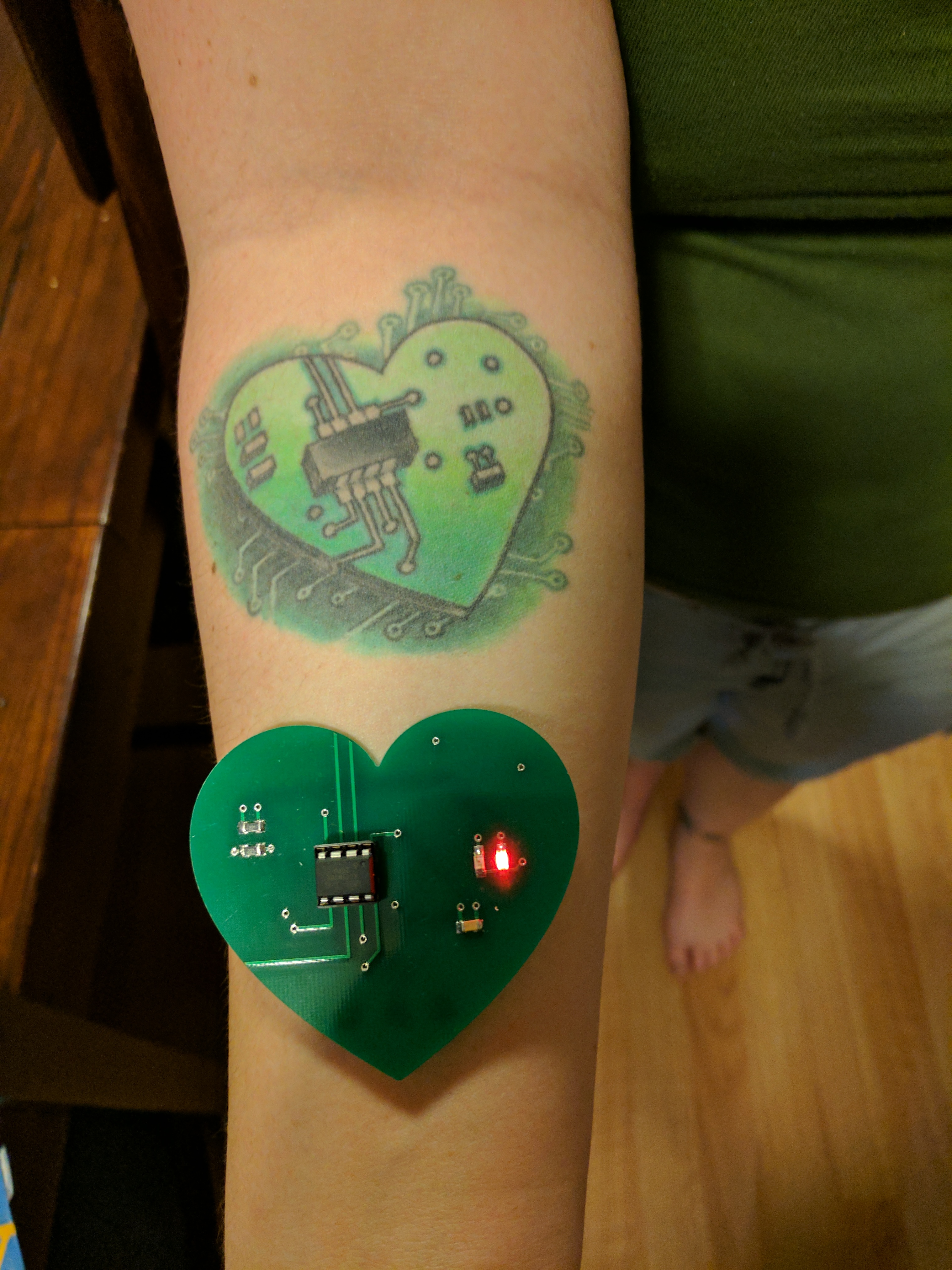
A few weeks later was Missa’s birthday party, so I was finally able to give her the board! She loved it!
I was really happy and a little surprised that I’d gotten the size right. The tattoo photo I had didn’t have any absolute size references. I ended up measuring the width of the depicted chip in the photo using Photoshop and scaling the rest of the design accordingly assuming the chip was 0.3” wide—the standard width of 8-pin through-hole chips. Amazingly, that led to a nearly perfectly-sized heart; the board lay over her tattoo almost exactly.
This was both a really fun project and a great learning experience!