USB Power Splitter
October, 2019
This is the story of my tiny contribution to a project that is mostly Liesl’s. She worked for dozens of hours making an amazing costume: a chandelier dress!

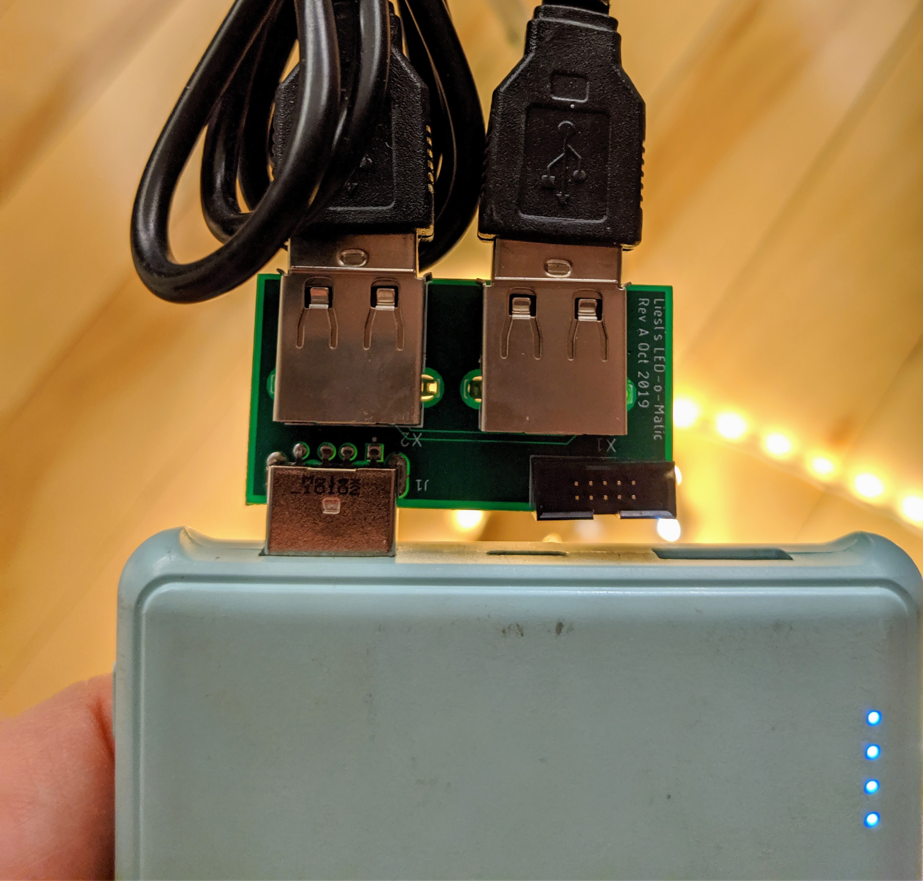
It has real lights on it – two long strips of bright white LEDs that have USB plugs. She made a little pouch to hold a 10,000 mAh USB power brick with two outputs, one for each LED strip. Each one plugged in individually worked fine. Unfortunately, when she plugged both in at the same time, they’d only turn on for a moment and then go dark. Each strip was individually drawing current at nearly the brick’s maximum output; with both plugged in, the brick was overloaded and shut itself down.
Of course, one way to fix this would be to put two power bricks in the dress, but they were bulky and there was barely room for a single one.
I came up with another solution: build a tiny circuit board that splits the power from the brick into two outputs, with half the current going to each one. In other words, it very quickly switches the power so it’s flowing between the input and one of the two LED strips, but the two outputs are never on at the same time. This cuts the power to each strip in half, letting us light both strips with what would normally be the power of a single strip. Since the LEDs are getting half the power of normal, they’re a little dimmer, but the nonlinear relationship of power to brightness means they’re still very bright.
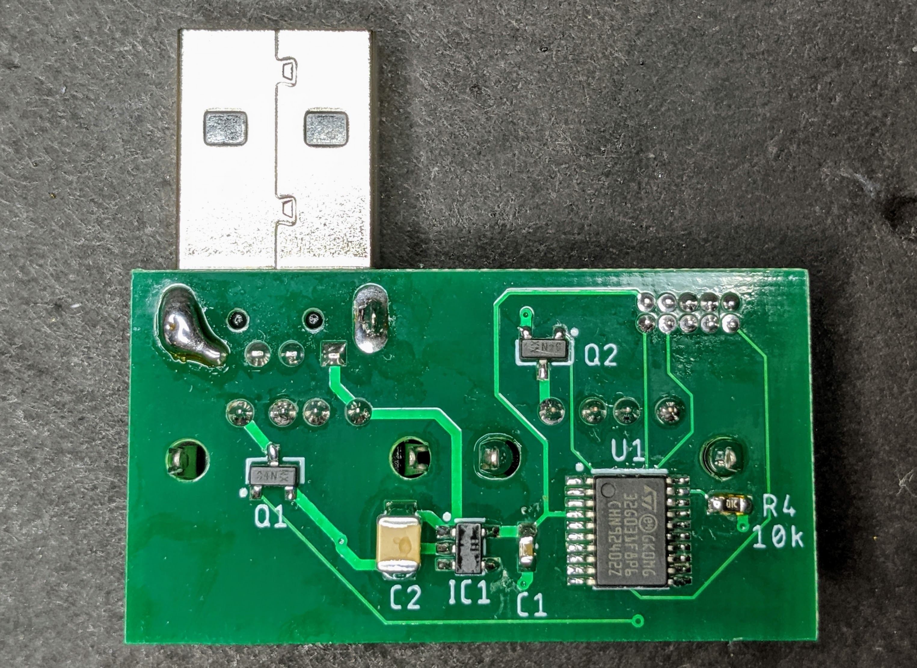
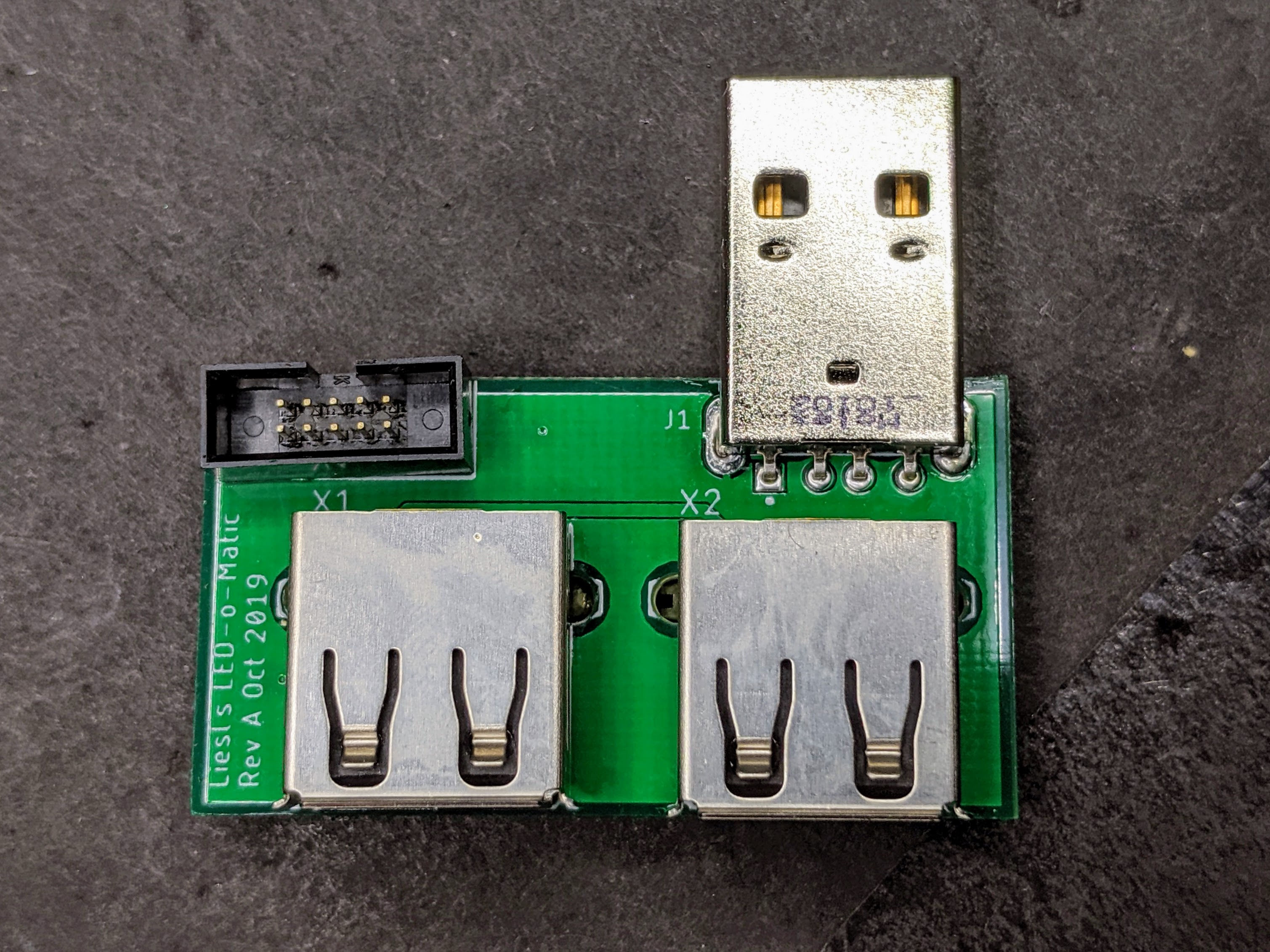
The circuit is extremely simple. A USB plug takes power input from the brick. Two USB jacks provide power output to the LED strips. The power to each plug is controlled by an N-channel MOSFET. Both MOSFET gates are controlled by a microcontroller that has a few lines of software on it that switches the outputs on and off. The time is divided into 7 time slots of 10 microseconds each. The left output is on for 30 microseconds, the right is on for 30 microseconds, then both are off for 10 microseconds. The entire cycle repeats every 70 microseconds, so the overall switching speed is about 15khz.
I used my favorite small microcontroller – the STM32G0. I love the whole STM32 product line; the G0 is their line of entry level CPUs that are perfect for this kind of thing. They are as small as your pinky fingernail, cost a dollar, require no external components, run at 64MHz and have every peripheral you could want.
The whole project took only two evenings. The first evening, I drew the circuit in Eagle and sent it to PCBway for fabrication. A week later, when the PCBs arrived, I soldered one together and wrote the software. I didn’t even have to buy any components; I had everything I needed in stock already.